
| Home | Contests | XC Pins | XC Gear | Links | |||
| XC Tech |
| Performace Testing | Minimize Slop |
Minimizing Slop in Control Surfaces
by Dieter Mahlein
Slop is a problem, especially in high-performance gliders. At best, slop makes flying more difficult; and at worst, it can lead to flutter which in turn may cause air frame failure.
There is "hard slop" and "soft slop." Hard slop is caused by play in the linkage, for example in the servo gears or at the clevis. Hard slop has clearly defined end points, is readily identified, and there are easy ways to minimize it, even after radio installation is complete. Soft slop is caused by something bending or deforming under load; it is a stealthy killer of air frames. Unlike hard slop, it may be difficult to detect during pre-flight procedures, it is difficult to eliminate, and it definitely can be a serious problem. Soft slop has no defined end points and varies in severity with the aerodynamic load on the glider. Soft slop must be prevented during construction and assembly of the air frame and installation of the radio gear.
Slop can occur anywhere in the control linkage: from the servo and the servo mount, through the linkage itself, to the control horn and the control surface.
Servos can have internal gear slop, and cheap servos tend to have more of it than quality ones. This is a source of hard slop, and there is nothing to do about it other than use good servos. Be aware that the gear trains of even the best servos will wear over time and develop slop. Changing the gears may not fix this completely because the pins on which some of the gears rotate have worn their bushings. Therefore, replacing the parts of the servo case which contain these bushings will help. A weak servo output arm can be a source of soft slop. Quality servos come with strong arms and for some, after-market metal or composite arms are available. Again, use quality servos with strong arms. Importantly, we can minimize soft arm and hard gear slop by attaching the linkage as far inside on the servo arm as possible. Ideally, adjust the linkage such as to use 100% of the available servo travel. Be aware that electronic mixes, particularly on ailerons and flaps, use up servo travel. Thus, having a strong arm which allows attaching the linkage a little farther out than minimal makes set up easier.
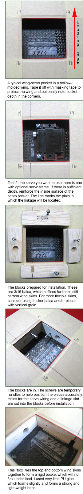
Slop in the servo mount occurs in sheeted and composite foam core wings and in molded wings where the servos are glued to the inside of the wing skin. Aerodynamic loads are transferred from the control surface via the linkage to the servo which flexes the wing skin. This is soft slop, it is as serious as it is hidden, and it must be eliminated during servo installation. The best way to do this is to box in the servo with braces which tie the wing's top and bottom skins together around the servo. Ideally, this box and the servo themselves are tied into a wing spar. If the wing is sufficiently thick, also reinforce the wing skin to which the servo is mounted.
Assuming we use common metal clevises (dont use plastic clevises on performance planes), linkage slop can happen between the servo arm and the clevis; in the push rod threads, if the clevis is threaded; and finally between the clevis and the control horn on the control surface. This is hard slop, and it is easy to fix with a few drops of CA. A drop of thin CA placed on the threads next to the clevis will eliminate all slop there. Of course, make sure the linkage is properly adjusted before CAing it. Likewise, a drop of thick CA placed at the junction between clevis and control horn or servo arm, when kicked, creates a bushing which eliminates slop without binding up the linkage. Don't worry, you can simply break loose the linkage and make the movement smooth and slop-free. This works for nylon, composite, or metal arms and horns, linked to metal clevises. Note that this CA bushing is necessary only if there indeed is slop at the clevis pin, so check for it before using this method.
At the control surface itself, make sure to use strong, rigid control horns. The common nylon ones are useless in performance gliders; use metal, composite or strong plywood horns instead. This way there is no bending or flexing, and you only have to deal with hard slop, if any. The bigger and heavier the control surfaces, the longer the lever of the horn should be. Always place horns and linkages opposite the side where the surface is hinged; this automatically increases leverage by the thickness of the control surface and minimizes horn length; for example, bottom-hinged flaps should be linked at the top.
For more information, I highly recommend Radio Carbon Art's F3 Building Clinic video, which, among other things, details proper linkage construction and geometry. This video, and the one called Performance Tuning, contain valuable information for anyone wishing to optimize their gliders' performance.
| Home | Contests | Organize a Contest | Contests Galley | XC Pins | XC Gear | XC Tech | Links | |